Lab 2
- Intro to Electronics
- GPIO basics
- Controlling an LED
- Controlling the brightness of an LED using pulse-width
modulation (PWM)
- Making sound using a piezo buzzer
- Building user interfaces to control your Pi apps
Intro to Electronics
http://www.instructables.com/id/Basic-Electronics/***
(steps 1 through 17)
https://learn.sparkfun.com/tutorials/voltage-current-resistance-and-ohms-law***
GPIO basics and installing RPi.GPIO
Go through recipes 9.1 and 9.2.
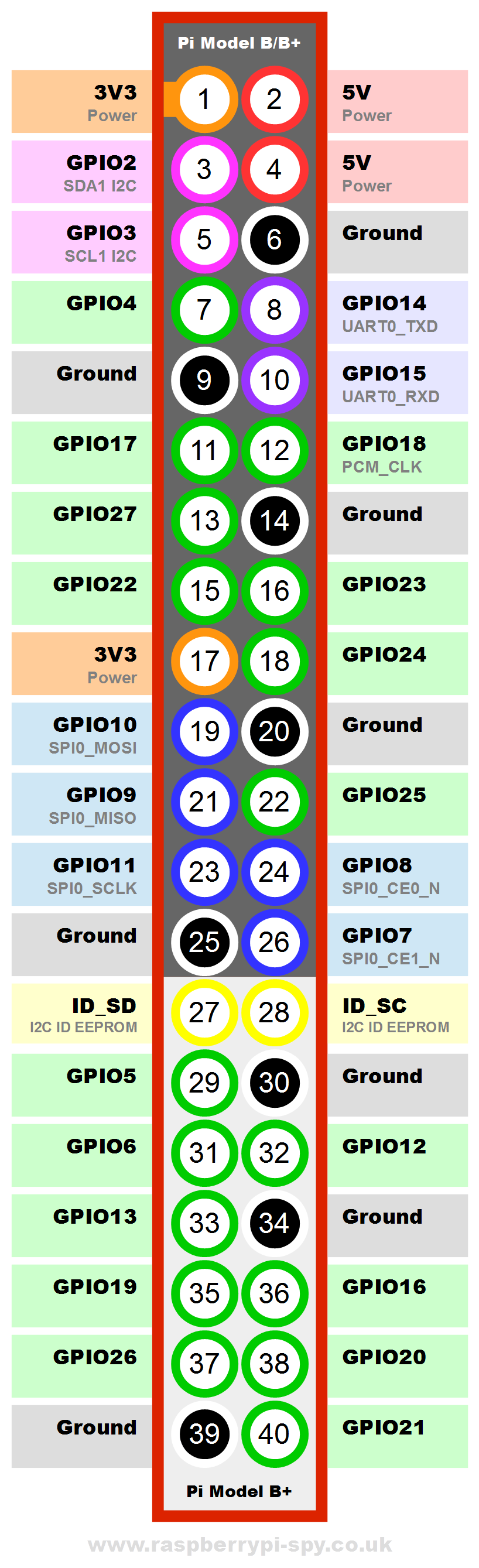
Note that the Raspberry Pi 3 model B we are using has 40
pins and its pin layout is:
Connecting an LED
Do recipe 10.1. Start by creating the circuit shown in Figure 10-1.
Note that the LED must be placed so that it's longer pin is on the
high side (3.3V) of the circuit (rather than ground or 0V).
WARNING: Make sure your are using a series resistor in the
circuit containing the LED.
With a voltage of 3.3V and a 1kOhm resistor, Ohm's Law says that the
amount of current I through the LED satisfies the equation 3.3 volts
= I x 1000 ohms so the amount of current going through the LED is no
more than 3.3/1000 = .0033 amps or 3.3 milliamps.
To test your set up, you can move the wire going from pin GPIO18 to
a 3.3V pin; if you do so, the LED should light up. Once you have
made the check, replace the wire back on pin GPIO18.
The code on page 241 that gets
the LED blinking is:
import RPi.GPIO as GPIO
import time
GPIO.setmode(GPIO.BCM)
GPIO.setup(18, GPIO.OUT)
while (True):
GPIO.output(18, True)
time.sleep(0.5)
GPIO.output(18, False)
time.sleep(0.5)
Functions from module RPi.GPIO:
- setmode()
: There are two ways of numbering the I/O pins on a Raspberry Pi
within RPi.GPIO. We will be using the numbering system
BCM defined by BCM numbers (defined by the chip
manufacturer Broadcom). The BCM numbers are those following the
word GPIO in the above figure.
- setup(): Any pin you are using must be set up as an
input (IN) or output (OUT) pin; in this
recipe, we are setting the pin as an output pin.
- output(): sets the state of an output pin.
For more detailed info, see the documentation for the RPi.GPIO
module at
http://sourceforge.net/p/raspberry-gpio-python/wiki/BasicUsage/
***
Read also
http://sourceforge.net/p/raspberry-gpio-python/wiki/Outputs/
***
The code on page 241 can be
typed up using the IDLE IDE. Alternatively, you can download all the
books code by following recipe 3.19, i.e. using the following shell
command:
$ git clone
https://github.com/simonmonk/raspberrypi_cookbook_ed2.git
Raspberry Pi Cook
(See recipe 3.20 for more info.)
The code on page 241 is the program led_blink.py.
You must run it in superuser mode which you can do by opening IDLE3
as a superuser by typing
$ sudo idle3
and then opening the file led_blink.py
from within IDLE3. Alternatively, you can run it directly in the
command line shell as follows:
$ sudo python3 led_blink.py
Leaving the GPIO pins in a safe state
Do recipe 10.2.
Raspberry Pi Cookbook
Controlling the brightness of an LED using pulse-width
modulation (PWM)
Raspberry Pi's GPIO pins do digital I/O rather than analog I/O. In
other words, they can output or sense (for input pins) either 0V or
3.3V but nothing in between.
Pulse Width Modulation, or PWM, is a technique for getting
analog results with digital means. Digital control is used to create
a square wave, a signal switched between on and off. The
number of times the signal is on during 1 second is the PWM frequency;
it is expressed in Hertz or Hz.
This on-off pattern can simulate voltages in between full on (3.3
Volts) and off (0 Volts) by changing the portion of the time
the signal spends on versus the time that the signal spends off. The
duration of "on time" is called the pulse width and the
percentage of "on time" is the duty cycle. To get varying
analog values, you change, or modulate, that pulse width (or duty
cycle). If you repeat this on-off pattern fast enough with an LED
for example, the result is as if the signal is a fixed, steady
voltage between 0 and 3.3v controlling the brightness of the LED.
(From http://arduino.cc/en/Tutorial/PWM.)
Do recipe 10.3 which illustrates how to use PWM on a Pi. You will
run program led_brightness.py
which you can do as described in the book or from within IDLE3 as
explained above:
import RPi.GPIO as GPIO
led_pin = 18
GPIO.setmode(GPIO.BCM)
GPIO.setup(led_pin, GPIO.OUT)
pwm_led = GPIO.PWM(led_pin, 500)
pwm_led.start(100)
while True:
duty_s =
raw_input("Enter Brightness (0 to 100):")
duty = int(duty_s)
pwm_led.ChangeDutyCycle(duty)
Functions from module RPi.GPIO:
- PWM(): constructor that creates a PWM instance; the
frequency of the square wave is specified here.
- start(): starts PWM instance; takes the initial duty
cycle as an input argument.
- ChangeDutyCycle(): changes the duty cycle.
For more detailed info, see
http://sourceforge.net/p/raspberry-gpio-python/wiki/PWM/
***
Making a sound using a piezo buzzer
Do recipe 10.4 to see how to control electronics other than LEDs.
The code you will execute is:
import RPi.GPIO as GPIO
import time
buzzer_pin = 18
GPIO.setmode(GPIO.BCM)
GPIO.setup(18, GPIO.OUT)
def buzz(pitch, duration):
period = 1.0 /
pitch
delay = period
/ 2
cycles =
int(duration * pitch)
for i in
range(cycles):
GPIO.output(buzzer_pin, True)
time.sleep(delay)
GPIO.output(buzzer_pin, False)
time.sleep(delay)
while True:
pitch_s =
raw_input("Enter Pitch (200 to 2000): ")
pitch =
float(pitch_s)
duration_s =
raw_input("Enter Duration (seconds): ")
duration =
float(duration_s)
buzz(pitch,
duration)
Building user interfaces to control your Pi apps
You may want to control your Pi applications using GUIs rather than
the IDLE interpreter.
Do recipes 10.8, 10.9, and 10.10 to see examples of this. Note that
recipe 10.10 uses a RGB LED rather than a plain RED LED.
For a refresher on developping GUI apps with tkinter, see Chapter 9
of your CSC 241/242/243 textbook or https://docs.python.org/3/library/tkinter.html.
Charlieplexing
Do recipe 10.11.
This recipe illustrates how electricity will flow when several
output and input pins are tied in a circuit. The flow will be from a
high output pin to a low output pin. Input pins can detect voltage
but no electricity flows through them.
Homework
Re-read the recipes in the textbook we have covered in Lab 2. Also
go through the starred (***) online tutorials and online
documentation covered in Lab 2.