Lab 3


Using GPIO pins for input

Do recipes 12.0, 12.1.

To understand this example, we need a bit of background. When a GPIO pin is set as an input it is “floating” and has no defined voltage level. For us to be able to reliably detect whether the input at the pin is high or low (voltage) we need to tie it in a closed circuit so that it is always connected and either reads high or low. To tie the pin we connect it with a Pull Up or Pull Down resistor. This can be done in hardware using a parallel circuit (see below). On the Raspberry Pi, this can be done in software so no additional hardware circuit needs to be created.

A Pull Up resistor (illustrated in the first of the two diagrams below) connects the GPIO IN pin to 3.3V through a large resistor (R1), which means that when the switch (Switch 1) is open (i.e., not pressed) there is a path from 3.3V to the GPIO IN pin and the GPIO IN pin will read high (1 or True). When the switch is pressed (with the other side connected to ground or 0V as shown in the figure), there is a lower resistance path to ground (low or 0V)  and then the pin will read low (0 or False). The large resistance (10kΩ) of the R1 resistor ensures that only a little current is drawn when the switch is pressed.


(Diagrams from eLinux )

A Pull Down resistor (illustrated in the second of the two diagrams above) connects the GPIO IN pin to ground (0V) through a large resistor (R1), which means that when the switch (Switch 2) is open (i.e., not pressed) there is a path from 0V to the GPIO IN pin and the GPIO IN pin will read low (0 or False). When the switch is pressed (with the other side connected to 3.3V as shown in the figure), there is a lower resistance path to high and then the pin will read high (1 or True).

New function from module RPi.GPIO:
For more info, see
http://sourceforge.net/p/raspberry-gpio-python/wiki/Inputs/ ***
http://pythonhosted.org/RPIO/rpio_py.html#gpio-input-output ***


Turning something on and off using a switch

Do recipe 12.2 and then 12.5.


Programming with interrupts

Do recipe 10.13. This recipe describes an alternative to the polling approach we have been using to detect switch presses. But first, why do we need an alternative?

In the polling approach, we repeatedly check the state of the input pin in a loop and when a particular state is detected (the event) we execute some event handling code:

while True:
    if GPIO.input(18) == False:
        # put the event handling code here
    time.sleep(0.1)
In the above program, the state of pin 18 is originally high (1 or True). When the switch is pressed, the state of pin 18 goes low (a value of 0 or False) and the event handling code is executed. The instruction time.sleep(.1) is used to add a slight delay to the program, giving other tasks on the system time to run.

The problem with the polling approach is that the CPU is very busy running the loop even when the switch is not being pressed for long periods of time. It also means that the program cannot anything else why in the loop. This "busy waiting" also takes CPU processing time that could be used for other processes running on the Pi which effectively slows them  down or even prevents them from running. Finally, with the above code, it is technically possible that a button press can be missed if the signal goes to 0 and then returns back to 1 before the input state is checked again. This is especially likely if the timeout is longer than 0.1s, the input is a pulse shorter than 0.1s, or there are other actions occurring in the while loop.

The alternative to the polling approach is the interrupt approach. In this approach, you specify a function that is run (i.e. called) as soon as the input changes state. This function is known as a callback function. The GPIO library keeps a separate thread for all interrupt callbacks, and the callback functions are serialized (run one at a time) on this separate thread. To use these interrupts, first setup the callback and associate it to the pin using RPi.GPIO function add_event_detect().

New functions from module RPi.GPIO:

For more detailed info, see
http://sourceforge.net/p/raspberry-gpio-python/wiki/Inputs/ ***


Using an external pull-up resistor

Do recipe 12.6. Test your code using program switch.py from the textbook.

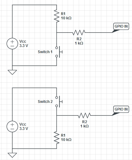
Exercise: When done, change the circuit to a pull-down resistor and modify switch.py appropriately to test your circuit. Important: the circuit you want to build is the second of the above two circuits and make sure that you use a 10kOhm and a 1kOhm circuit as shown above. Make sure to call me to verify your circuit before you connect the wire to the 3.3V pin.

 To verify the resistance of a resistor, you will find this online resistor color code calculator helpful:

http://www.digikey.com/en/resources/conversion-calculators/conversion-calculator-resistor-color-code-4-band


Using a rotary encoder

Do recipe 12.7. For more info, read:
http://en.wikipedia.org/wiki/Rotary_encoder#Incremental_rotary_encoder ***


Detecting movement

Do recipe 12.9. For more info on Passive Infrared Sensors (PIRs) see
http://en.wikipedia.org/wiki/Passive_infrared_sensor ***
The program pir.py, mentioned in the book, is mission from the book's code. To get the program, do
$ wget http://reed.cs.depaul.edu/lperkovic/csc299/lab3/pir.py
In the next two exercises, you will modify program pir.py so that, when motion is detected, a photo is taken and an email is sent to you.


Sending email from Python

Do recipe 7.16. Download the code using
$ wget http://reed.cs.depaul.edu/lperkovic/csc299/lab3/sendmail.py
Raspberry Pi Cookbook
This command should be typed from within the directory in which you want to download the program.

Make sure to modify the values of GMAIL_USER and GMAIL_PASS appropriately. Please insure that the password of the gmail user is kept confidential.

For more info on the smtplib Python Standard Library module see
https://docs.python.org/3/library/smtplib.html
https://docs.python.org/3/library/smtplib.html#smtp-example ***
Exercise: When done, modify program pir.py from recipe 12.9 (and rename to pir_email.py) so that a short email is sent to you every time motion is detected.


Intercepting keypresses and mouse movements

Do recipes 12.11 and 12.12 (using the "Pygame" approach.)


Using the Raspberry Pi camera

Do recipe 1.14. Just test the commands raspistill and raspivid.

After taking a picture and a short video from the Linux shell, make sure that the camera Python API is installed
$ sudo apt-get install python3-picamera
$ sudo apt-get install python-picamera
For more info, see
http://picamera.readthedocs.org/en/release-1.12/install.html#raspbian-installation ***
http://picamera.readthedocs.org/en/release-1.12/quickstart.html ***
Download the Python program that illustrates how photos and videos are made from within Python:
$ wget http://reed.cs.depaul.edu/lperkovic/csc299/lab3/test_camera.py
Exercise: When done, modify program pir.py from recipe 12.9 (and rename to pir_photo.py) so that a photo is taken every time motion is detected.


Homework

Re-read the recipes in the textbook we have covered in Lab 3. Also go through the starred (***) online tutorials and online documentation covered in Lab 3.