 (from the textbook)
This command should be typed from within the directory in which you want to download the program.$ wget http://reed.cs.depaul.edu/lperkovic/csc299/lab3/sendmail.py
https://docs.python.org/3/library/smtplib.htmlExercise: When done, modify program pir.py from recipe 12.9 (and rename to pir_email.py) so that a short email is sent to you every time motion is detected.
https://docs.python.org/3/library/smtplib.html#smtp-example ***
$ sudo apt-get install python3-picameraFor more info, see
$ sudo apt-get install python-picamera
http://picamera.readthedocs.org/en/release-1.12/install.html#raspbian-installation ***Download the Python program that illustrates how photos and videos are made from within Python:
http://picamera.readthedocs.org/en/release-1.12/quickstart.html ***
$ wget http://reed.cs.depaul.edu/lperkovic/csc299/lab3/test_camera.py
http://www.robotroom.com/Trimpots.html ***So the goal of this recipe is to measure the resistance of the trimpot. This recipe uses capacitors. You can think of a capacitor as a rechargeable battery. It has two metal plates separated by an insulating material. When tied to a circuit, the plate on the positive side stores a positive charge and the plate on the negative side stores a negative charge. No current passes between the plates though. The amount of charge stored on the plates is the capacity of the capacitor. For more info about capacitors see
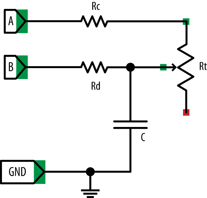
https://learn.sparkfun.com/tutorials/capacitors ***The circuit you build in this recipe is shown below:
The purpose of this circuit is to measure the resistance at the variable resistor Rt. When pin A is set to output high (3.3V) and pin B is set to be an input pin, then the capacitor will charge. The speed at which it will charge will depend on the amount of current between pin A and the capacitor which has to go through variable resistor Rt. When the resistance of the variable resistor Rt is decreased, the amount of current is increased and the capacitor will fill up more quickly; when the resistance is increased, the amount of current is decreased and the capacitor will fill up more more slowly. By keeping track of the time it takes for the capacitor to fill we can effectively "read out" the resistance at the variable resistor Rt and, therefore, the position of the trimpot dial.
https://learn.adafruit.com/photocells/ ***
Do recipe 13.3.
https://learn.adafruit.com/reading-a-analog-in-and-controlling-audio-volume-with-the-raspberry-pi/connecting-the-cobbler-to-a-mcp3008 ***The communication between the MCP3008 chip and the Pi is via the Serial Peripheral Interface, a full-duplex, synchronous communication protocol. For more info, read
https://learn.sparkfun.com/tutorials/serial-peripheral-interface-spi ***Do recipe 9.5 to get the Serial Peripheral Interface (SPI) enabled if you have not done so already. Then do recipe 13.5. In the code, you will find function
import spidev, time
spi = spidev.SpiDev()
spi.open(0, 0)
Raspberry Pi Cookbook
def analog_read(channel):
r = spi.xfer2([1, (8 + channel) << 4, 0])
adc_out = ((r[1]&3) << 8) + r[2]
return adc_out
Of the 24 bits sent to the chip, only the bits 8-12 are relevant. Bits 8 and 9 contains 1 and bits 10, 11 and 12 (D2, D1, and D0) contain the channel number (0 through 7) in binary notation (000 through 111). In the example above, list [1, (8 + channel) << 4, 0] represents bits (signals)
00000001 10000000 00000000which requests the voltage at channel 0 (binary 000).
http://tightdev.net/SpiDev_Doc.pdfFor a more in-depth overview of SPI, see
http://en.wikipedia.org/wiki/Serial_Peripheral_Interface_Busas well as
http://www.byteparadigm.com/applications/introduction-to-i2c-and-spi-protocols/This last reference also discusses I2C, an alternative serial communication protocol. Finally, here is the all important MCP3008 datasheet:
http://www.adafruit.com/datasheets/MCP3008.pdfRecipe 13.6 shows how to read sensors that output a voltage outside the ususal 0 - 3.3V range.
