Controlling the Direction of a DC Motor
Do recipe 11.5, using option 1.
In this recipe the goal is to tie a DC motor in a H-bridge
circuit that will allow us to change is rotation direction
from within a Python program. Here is an illustration of an
H-bridge:
 (from the textbook)
When switches S1 and S4 are closed and S2 and S3 are open,
terminal A is positive and B is negative and the motor will
rotate. If S1 and S4 are open but S2 and S3 are closed, then
terminal A is negative and B is positive and the motor will
rotate in the opposite direction.
An H-bridge can be built using several transistors.
Instead, we use the Texas Instruments L293D H-Bridge chip
which actually contains 2 H-bridges on each side of the chip
(allowing it to control 2 DC motors which we will make use
of with the raspirobot). This illustration explains the
wiring in Figure 11-8 used in recipe 11.5, option 1:
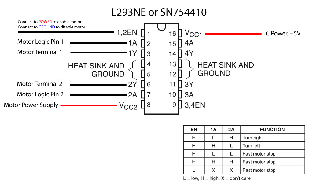 (from
instructables.com)
(from
instructables.com)